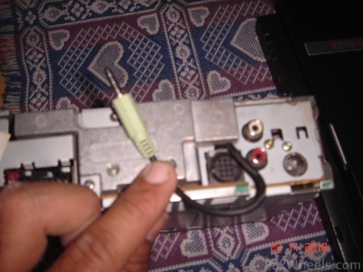
ok guys i successfully implented the same with my Kenwood KRC-265/KH4 ( KRC-265 model for honda ). i dit it at my office today so didnt have pics of unit opened, but i solded the resistor and stereo headphone cable to the circuit board directly and here is the outcome.
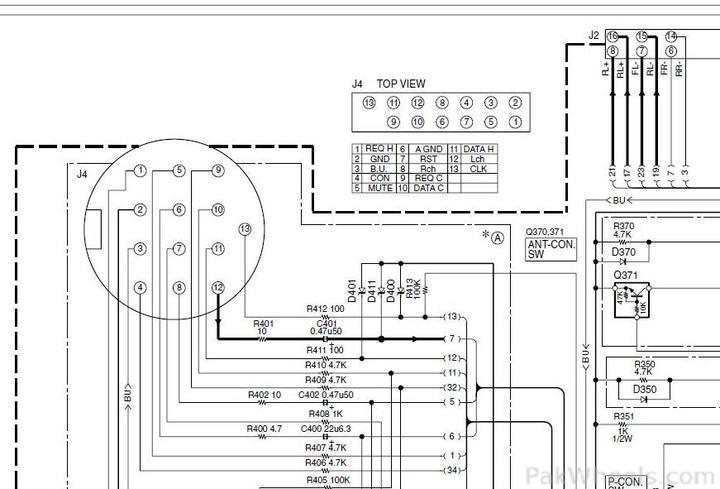
stereo cable i used was male to male headphone cable, and for detection of pins at circuit board i used the multimeter and following circuit diagram of same model,
the round J4 connector is the 13 pin din connector and on top of the pic is the pinouts of same at circuit board. so some delicate soldring and we are good to go. now i use a male to female stereo cable to connect it to its input device.
I have tested the setup with FM modulator and nokia express music and sound quality is hell lot of better as compared to FM modulator.
do let me know if details pics are required, i'll open the unit and take em, but in few days time, as my headunit is still laying on my table after testing and yet to be fixed properly to the dashboard.
and many many thanks to the Redbull (H)
Edit: I used 1 watt 10K ohm resistance for the project which costed me Rs.2, and male female cable for Rs. 35, and one i connected to the circuit board was found at home laying around.
Edit once again: circuit diagram is valid for kenwood models KRC-225, KRC-235 and KRC-265
here i go with another edit 
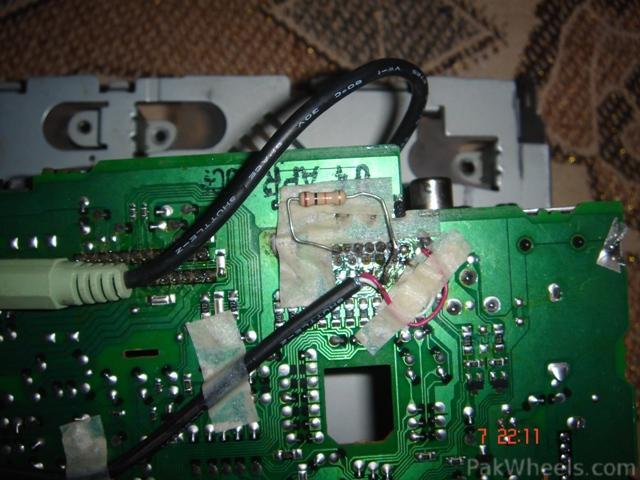
Opened up my player yesterday to change the drive belt, and i took off the main board too to take the following pic showing how its done, me not good at soldering but it works