For those who might be wondering how they work, here's an explanation.
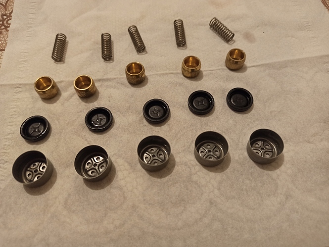
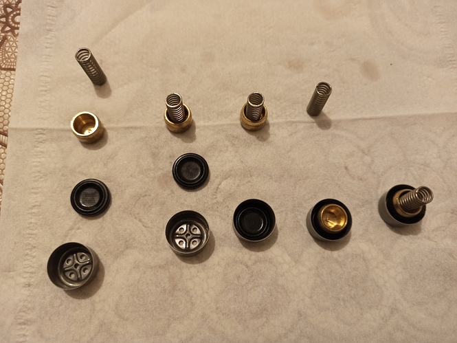
The photo below shows how they are assembled. Left most switch show un-assembled view just like in last post and right most switch is completely assembled.
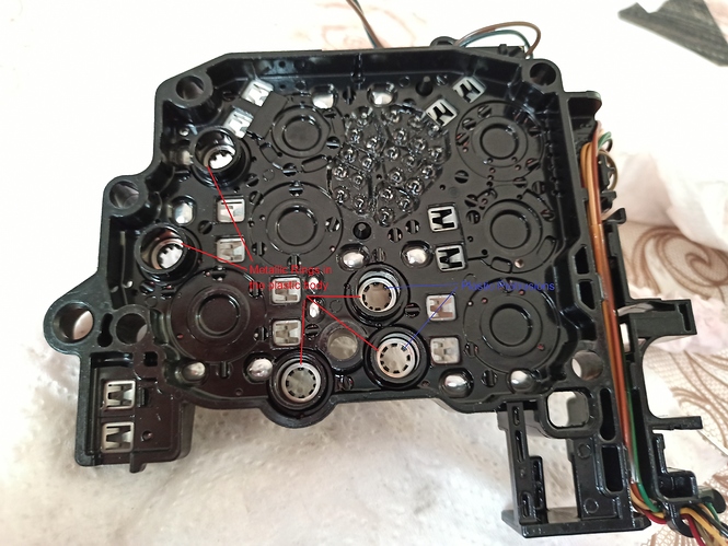
These switches work as clapper valves. In normal state, the springs push the brass contacts on to the diaphrams which is placed on the metallic caps with 4 holes. When pressurized, the diaphragms push the brass contacts back towards the springs and hits a metallic rings embedded in the plastic chassis as shown below in the red. PCM sees these metallic rings in the plastic body as 300ohm resistance; when the brass contacts hit the metallic rings, the PCM sees a ground via (rings)-(brass contact)-(spring)-(metallic plate on top of black housing) route. This is how these clapper valves/pressure switch works.
Note the black protrusions in the plastic housing shown in blue. They are meant to prevent springs touching the metallic rings. If they break, PCM will see a shorted pressure switch all the time.