Aoa Everyone,
I thought I’d share a project I’ve been working on over the past month. There are many eagle-eyed and knowledgeable users here that have pointed out that electric turbos like this one:
https://www.aliexpress.com/item/32974694625.html?spm=a2g0o.productlist.0.0.48de3ad7ni9eHm&algo_pvid=d4e88583-0405-4d59-a285-bab02b4950c4&algo_expid=d4e88583-0405-4d59-a285-bab02b4950c4-5&btsid=0ab6f82c15867675663717834e3763&ws_ab_test=searchweb0_0,searchweb201602_,searchweb201603_
are scam and they are absolutely right! And some better built examples like this one:
https://www.aliexpress.com/item/1000006724572.html?spm=a2g0o.productlist.0.0.13c52144200k6z&algo_pvid=5e2c5f37-60ba-4d59-b238-a6a212659f67&algo_expid=5e2c5f37-60ba-4d59-b238-a6a212659f67-2&btsid=0ab6fab215867673444393188e7371&ws_ab_test=searchweb0_0,searchweb201602_,searchweb201603_
are also very doubtful if they can really shift more air than a typical engine of say 1.0-1.8L displacement can breathe on it’s own.
I have done some research and we can use simple math to determine how much air (or cubic feet per minute CFM) a naturally aspirated engine draws in at any rpm. The formula is also on Garret Turbos website and is a simplified formula:
CFM@ any rpm = {(Engine Capacity in L) x (Engine at that particular rpm) * (Volumetric Efficiency in %)}/56.63
With advancements in engine technology, modern engines have a volumetric efficiency of about 85%. This is directly tied to what we call pumping loss. In order words, it’s the actual amount of air that is drawn by the cylinders compared to its volumetric size. So for example a 1.5L engine with a volumetric efficiency of 85% spinning at 6000rpm has an air flowrate of 135CFM. In order to generate more power via force induction with this 1.5L engine, we need to generate airflow greater than 135CFM. A normal 3 inch tin blade fan can realistically never spin fast enough to generate that kind of air flow.
If you pump in more airflow than the engine can breathe in, you create boost. The turbine inside an actual turbo housing is spinning at +100,000rpms to compress the air and generate airflows that eventually lead to boost. Compressor maps of different turbo models will give you all the information you need to appropriately size and select a turbo to an engine size and max rpm. I am not going to go into that for this topic. Go and google research it. It’s fascinating if you are nerdy like me.
Now there are companies like Phantom Electric Supercharger and TorqAmp that build these electric superchargers ( https://www.youtube.com/watch?v=7a_J2X88fSE&t=1325s) with ultra-high speed brushless electric motors that are rated at around 4kW! That should give you an idea how much energy it takes to compress the air. 4kW @ 12V (the electrical system voltage of a car) equals around 333Amps of current! The alternator in the car cannot provide this much current to power to compress the air. Hence, another reason why these cheap electric turbos you see on ebay and aliexpress are scam. The Phantom Electric Supercharger and TorqAmp solutions have their own battery systems that get charged from the alternator whenever the boost is not required.
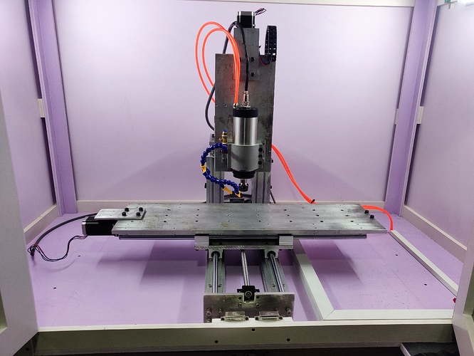
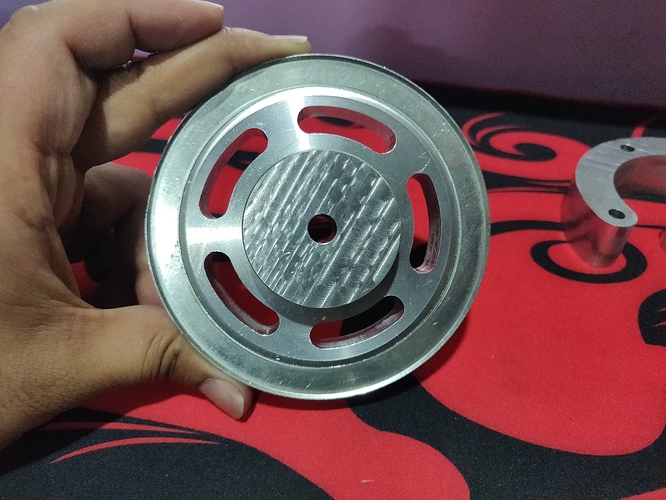
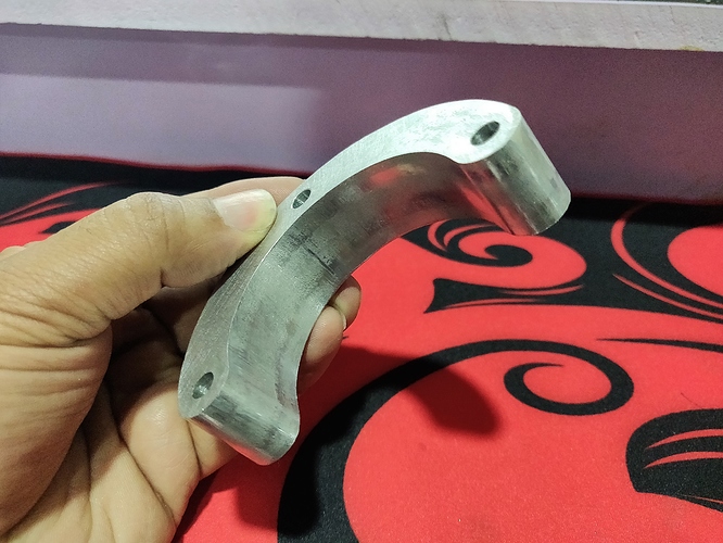
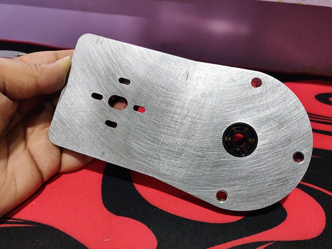
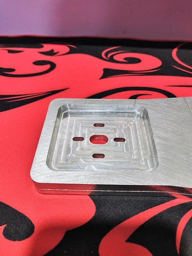
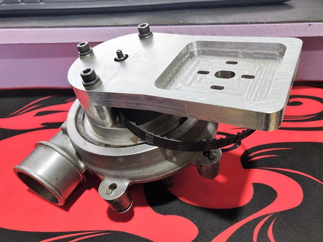
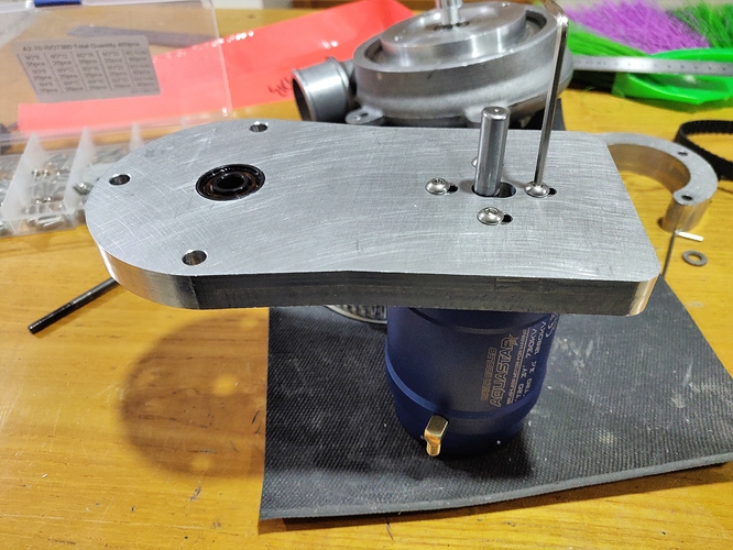
Taking inspiration from these guys, I am really interested to see if you can build your own electric supercharger because there are some advantages to this electric system over a traditional turbo setup. I have bought some of the components for this project and have used my own 5-axis CNC shop to fabricate some of the parts out of aluminum and mild steel. I’ll let some of the pictures do the talking….
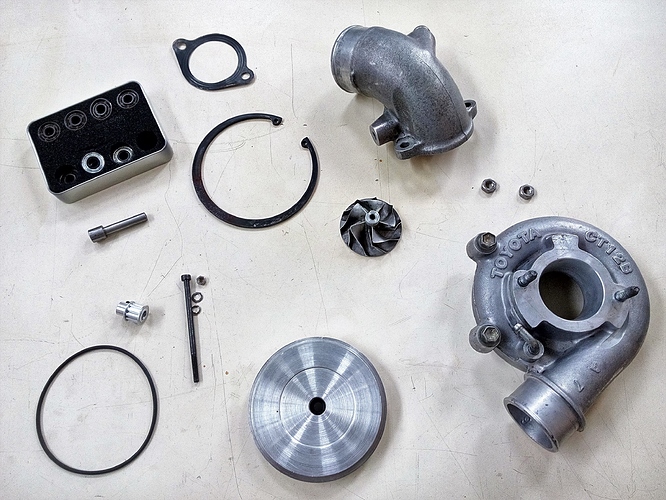
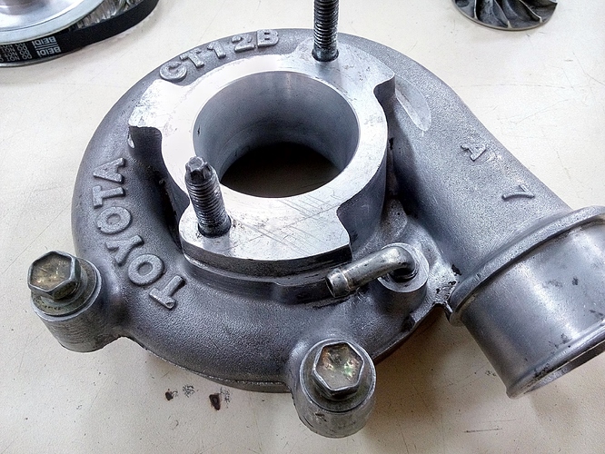
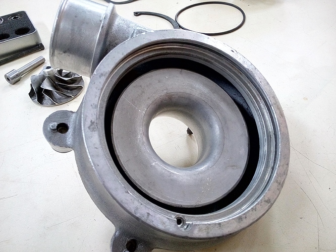
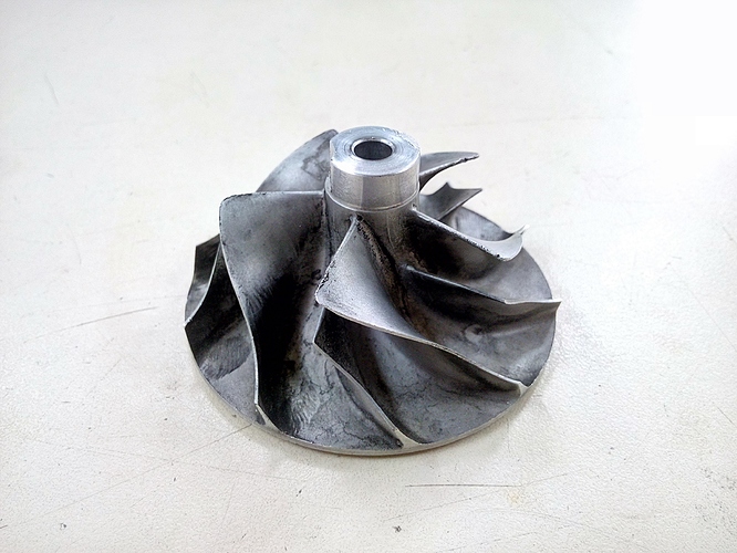
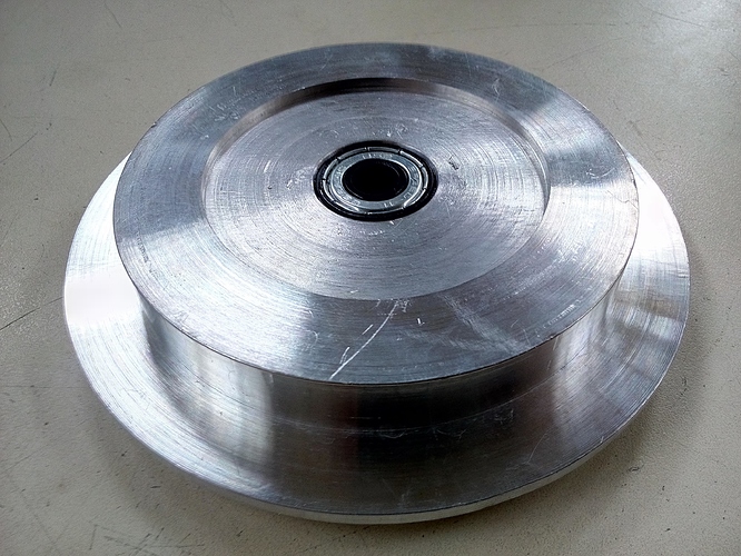
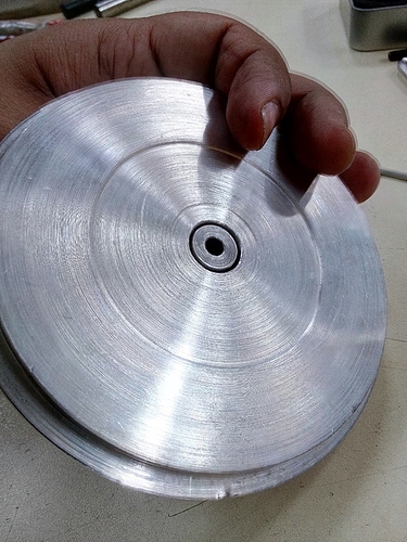
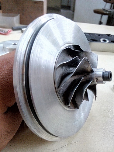
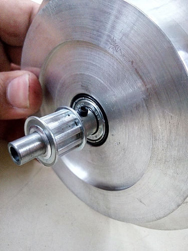
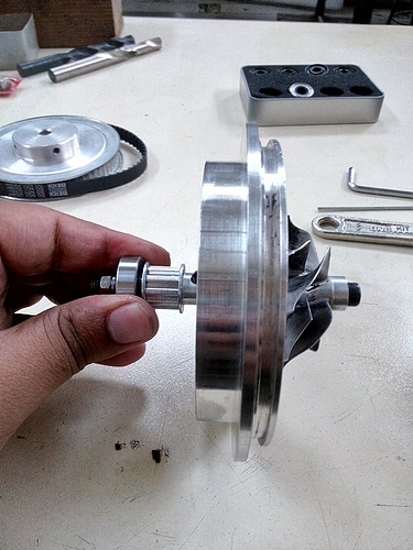
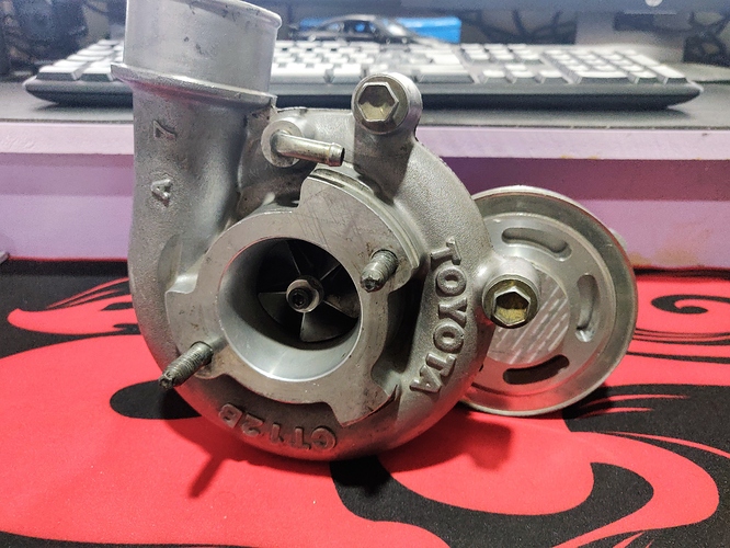
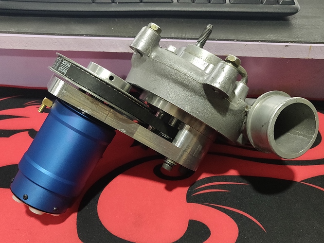
I bought a used Toyota CT12B turbo from Rawalpindi. I believe this turbo came fitted to the 3.0L diesel Prado engine and it also came fitted (in twin configuration) to the 2jz-gte! So one of these should be ideal for a 1.3L to 1.8L engine size. A smaller turbo would require stupid high turbine rpms (I am talking +200,000rpms) to create boost and a larger one would draw too much power to spin the turbine at even 50,000rpm.
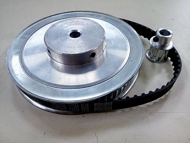
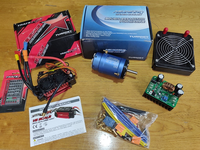
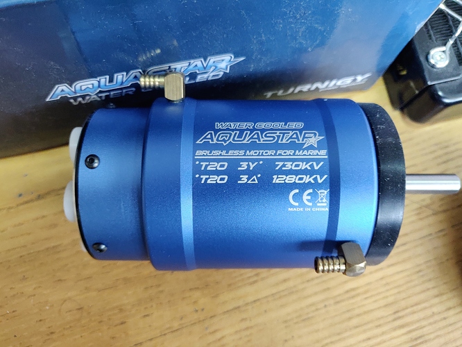
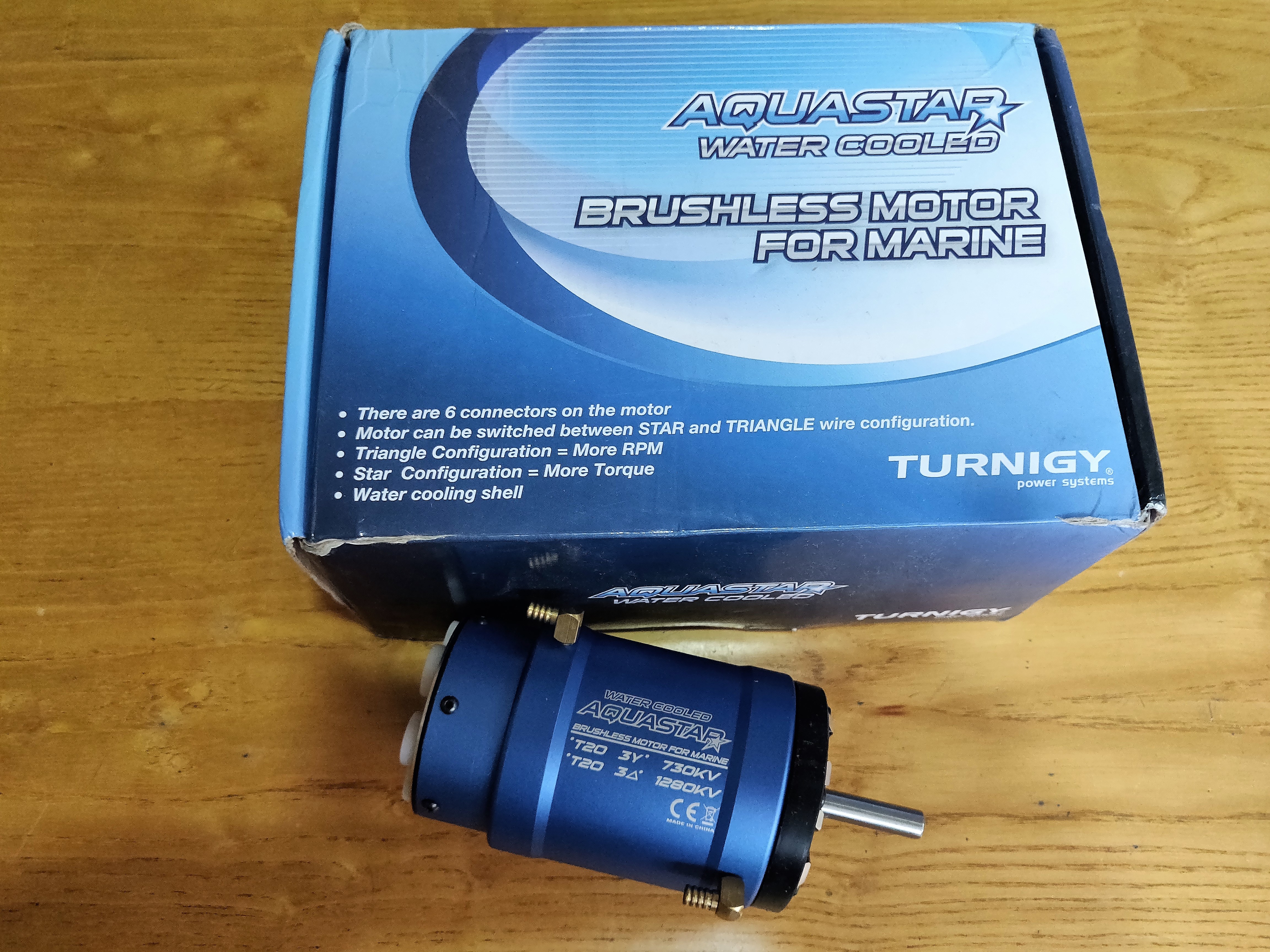
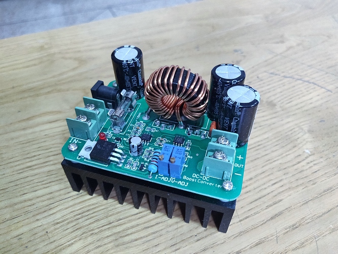
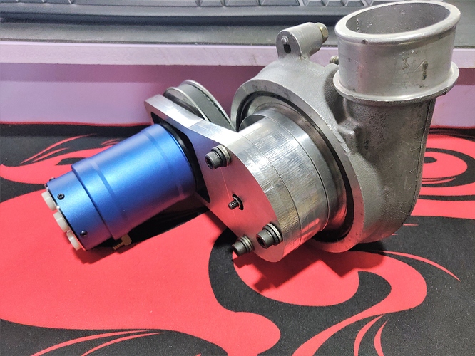
The system voltage is going to be 36Volts and I am going to use a DC-DC boost converter to charge the batteries from the alternator of the car. The motor of choice is brushless outrunner RC motor that can run on 36V and has RPM/V: 730KV rating. So at 36Volts, the output speed of the motor shaft is going to be 26,280rpm.
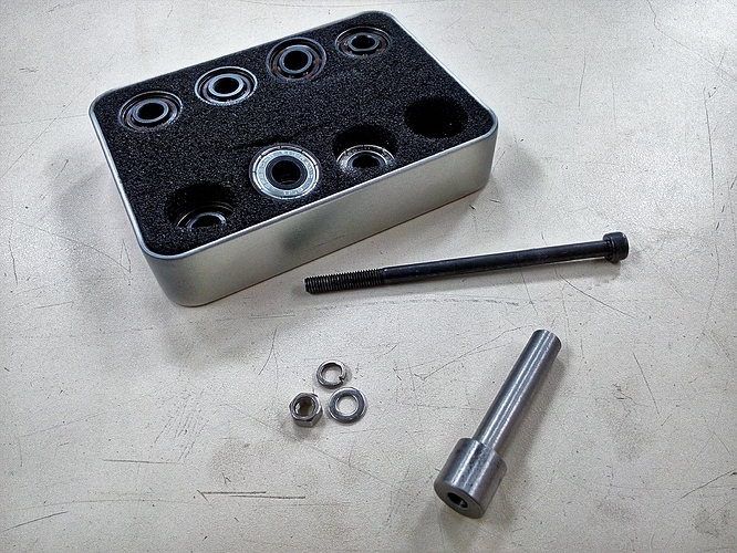
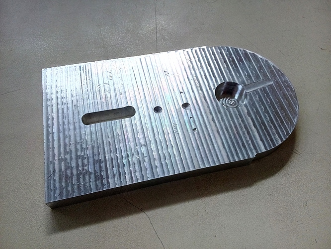
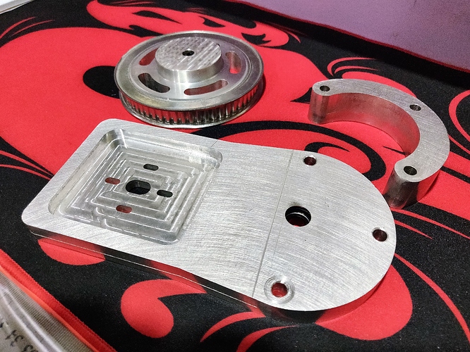
Everything is going to be housed in an aluminum frame that I am going to fabricate on my cnc machine. For bearings I am using ceramic bearings that can handle the heat generated from the high rotational speed. I won’t have to handle the exhaust heat as there isn’t any! The motor is connected to the compressor wheel via a 6:1 pulley belt system to increase the output speed to 157,000rpm. This should hopefully create boost and I literally sometimes have sleepless nights because I can’t wait to try it out!
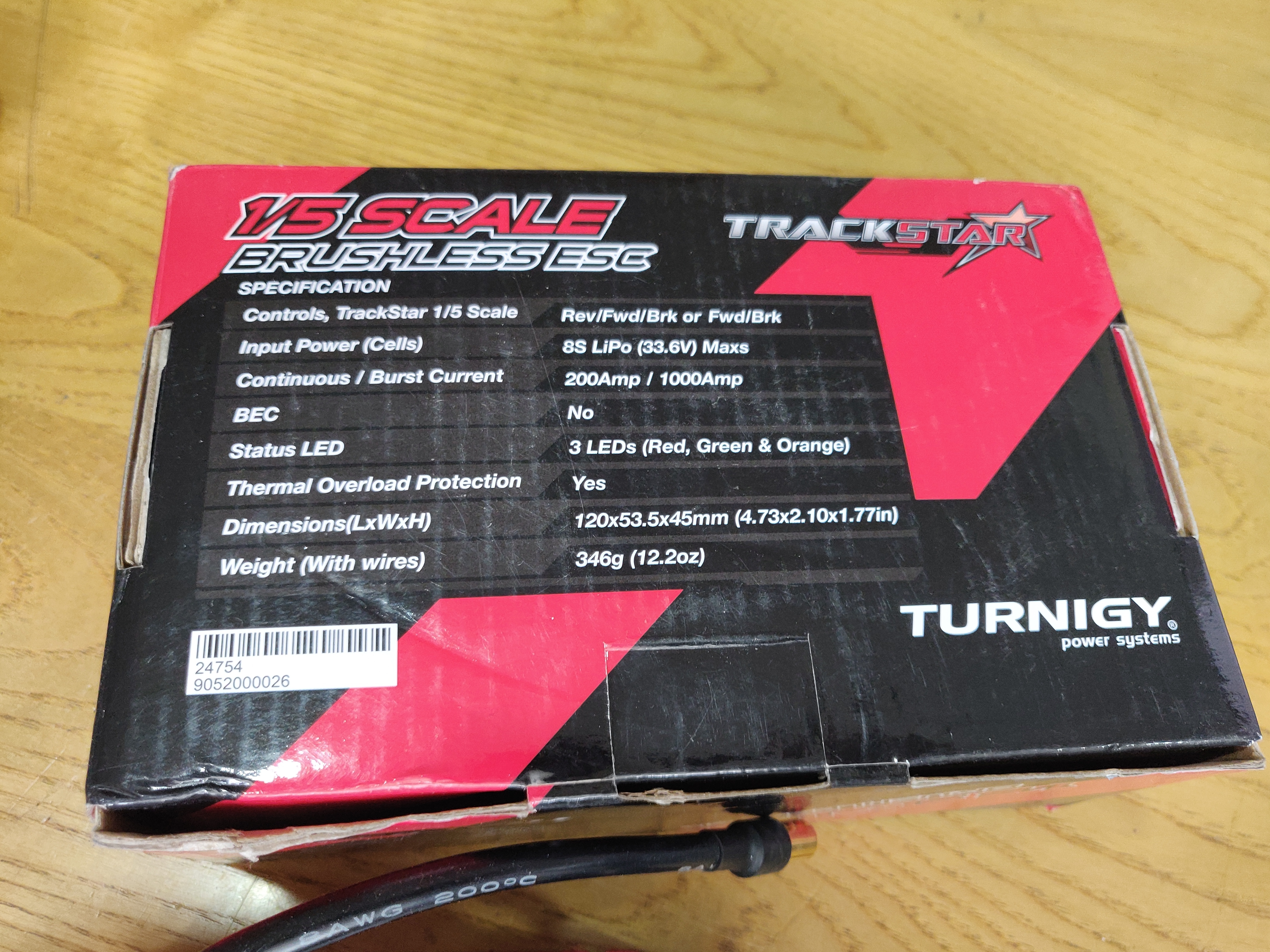
I am going to control the speed of the motor using a motor ESC and Arduino. The best way to determine the throttle position is to tap the potentiometer wire of the throttle position sensor mounted in the intake manifold of the car. My current car is a Honda City 1.5 Steermatic and I really don’t want to test it on this car because it’s CVT gearbox is not built to handle additional torque. I wish I had my old Nissan:
It would have been an ideal car for the project. Maybe my brother will lend me his Suzuki Swift  or is there someone in the audience who is willing to join in on the experiment with their car? I am looking to generate atleast 3psi boost across the rev range and that will hopefully not require an ECU tune as I am hoping the stock ECU and injectors have room to alter their pulse duration and timing.
This is currently work in progress as I said and will definitely keep you guys updated on the project. Stay safe and Indoors! Allah Hafiz