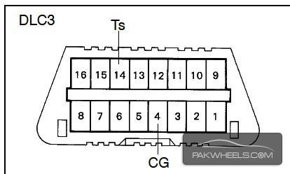
ok starting with the famous DLC3 connector
a ref picture is here so connect it properly.
ok here it is the 16 no connector in dlc3 is battery +ive
4-5 no pin is signal ground you can connect the both wire's togther and connect it to a good ground location.
7 no pin is signal from the ECU for communication.
8 no pin is ig+(ignition switch signal).
9 no pin is tachometer signal IG- signal. RPM signal. from the ECU
note the pin no 151 in the ecu is the data pin for communication. dont forget it and compare the diagram with the grip you had with you.