SG is the sensor ground that is used for the sensors and is generally in an isolated circuit from the power circuit so look for SG on the ECU. People often connect them together but its always a good idea to keep it separate if the ecu has that feature. I'm attaching another pinout for this ecu that has the SIL and TC in it but the position of TC and TACH are different from the one shared earlier. You need to open the case of the ecu to ascertain which pinout is the correct one for you. The pinouts are printed on the pcb, that is the most accurate way of going about it.
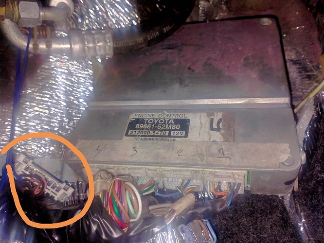
For the TACH wire, again, you need to check on the pcb print if the TACH pin is located on the pin in the earlier pinout or this one. You dont need to tap it on any other sensor, it is already available on the ecu. In case its at the location where there's no pin on the connector, you'll need to insert a pin into it, maybe a free one from any other connector that may not be in use for anything else.
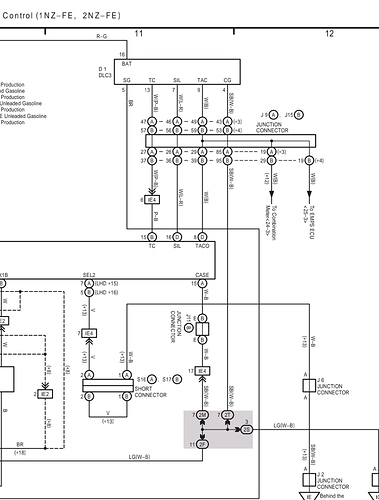
Here's the other pinout. (Check the bold part below to understand how to red the pinout against the image attached. Your ecu is the Type 2 Ecu)
ECU pinout
Under "connectors of the first type" (or simply "type 1") are meant connectors on Fielders 2000-2002. c., “second type connectors” (or simply “type 2”) means connectors on Fielders 2002-2004 . V. To begin with, the conclusions of the ECU themselves, in the
upper picture there are connectors of the first type, on the bottom - connectors of the second type:
Now about the assignment of all pins:
Uploading...
10 (#1 for "type 2") (pins A12 (type 1) - A1 (type 2)) - yellow (wire) - control of injector No. 1;
20 (#2) (A11 - A2) - black - nozzle control No. 2;
30 (#3) (A25 - A3) - white - nozzle control No. 3;
40 (#4) (A24 - A4) - blue - nozzle control No. 4;
- B (D12 - D1) - black - computer power supply, through the EFI relay;
AC (AC1) (D10 - C31) - yellow-black - input from the air conditioner on button;
ACLD (A1 - C33) - green-white - output to indicate the activation of the air conditioner (in the button);
ACMG (sometimes referred to as “MGC” in the diagrams) (D3 - C2) - yellow-red - output to the relay E / M of the air conditioning clutch;
ALT (A4 - B20) - red-black - input (output) from (to) the generator voltage regulator;
ALTC (D21 - A22) - black-yellow - input (output) from (to) the generator voltage regulator;
BATT (D1 - D3) - red-white - constant power supply to the computer;
CASE (EC) - white-black - ground (also contact "CG" in the diagnostic connector);
CF (A7 - D6) - light green - control of relay No. 1 of the electric fan;
D (C8 - C10) - blue-black - signal about the inclusion of the "D" mode on the selector (from the start prohibition switch);
E01 (A13-A7) - white-black - ground;
E02 (A26-A6) - white-black - ground;
E1 (A14-B7) - brown - mass;
E2 (B9 - A28) - brown - mass;
ELS1 (D6, only for "type 1", for "type 2" see "INHH") - green - signal to turn on side lights;
ELS2 (D4, only for "type 1", for "type 2" see "INHH") - white-red - signal to turn on the rear window heater;
ELS3 (D2, only for "type 1", for "type 2" see "INHL") - blue-yellow - a signal to turn on the heater fan, as well as to turn on the "idle boost system relay" (I and I don't understand what relay it is.
EMPS (B12 - B29) - blue-red - input signal from the EUR control unit;
EVG (B10 - B32) - blue-white - output to the DMRV;
EVP (PRG) (A9 - A12) - blue-black - control of the electro-pneumatic valve of the fuel vapor recovery system;
FAN (A8 - D7) - light green-black - control of relay No. 2 of the electric fan;
FC (D14 - D10) - green-red - fuel pump relay control;
G2 (G2+) (A18 - A26) - black - camshaft position sensor input;
GSFC (F / PS) (B7 - D14) - yellow - input (output) from (to) the SRS control unit;
HT (HTL) (B8 - B4) - pink - oxygen sensor heating control;
IGF (IGF1) (A3 - A23) - blue-yellow - input signal from the ignition coils;
IGT1 (A22 - A8) - red-blue - ignition coil control No. 1;
IGT2 (A21 - A9) - yellow-green - ignition coil control No. 2;
IGT3 (A20 - A10) - gray - ignition coil control No. 3;
IGT4 (A19 - A11) - white - ignition coil control No. 4;
INHH (C6, only for "type 2") - black - similar to the inputs ELS1 and ELS2 of the first type of connectors, but both signals are combined into one through diode isolation.
INHL (D13, only for "type 2") - partially similar to the ELS3 input of the first type connectors, but there is no signal to turn on the "idle speed control system relay" (as well as the relay itself).
KNK (KNKL) (B13 - B1) - black - input from the knock sensor;
L (D19 - C8) - light green-black - signal about the inclusion of the "L" mode on the selector (from the start prohibition switch);
NE- (A16 - A34) - white - common output for camshaft and crankshaft position sensors;
NE + (A17 - A27) - black - crankshaft position sensor input;
NSW (D22 - B8) - black-red - a signal that the selector is turned on to the "P" or "N" position, and, accordingly, that the start is allowed.
NT- (C11 - B35) - black - output (-) from the automatic transmission input shaft speed sensor;
NT + (C5 - B27) - white - input (+) from the automatic transmission input shaft speed sensor;
OCV- (A23-A14) - black-yellow - VVT valve control (-);
OCV + (A10 - A15) - yellow - VVT valve control (+);
ODLP (D7 - C7) - light green - output to turn on the "O / D OFF" indicator;
ODMS (C4 - C29) - light green-red - input from the overdrive on / off button (OverDrive);
OIL (C10 - A30) - white-blue - input from the automatic transmission fluid temperature sensor;
OX1A (OXL1) (B6 - B23) - red - input from the oxygen sensor;
PRS (HP) (D13 - A13) - yellow-black - input from the switch for high (low) pressure in the air conditioning system;
R (D4 - C11) - red-black - signal about the inclusion of the "R" mode on the selector (from the start prohibition switch);
RSD (A2 - A5) - black-blue - output to the idle speed control valve;
S1 (C3 - B15) - red-yellow - control of the valve "S1" of the automatic transmission electronic control system;
S2 (C9 - B14) - blue - control of the valve "S2" of the automatic transmission electronic control system;
SIL (D16 - D18) - yellow-red - contact "SIL" of the diagnostic connector;
SLT- (C7 - A16) - pink - valve control "SLT" (-) of the automatic transmission electronic control system;
SLT + (C1 - A17) - red-white - valve control "SLT" (+) of the automatic transmission electronic control system;
SLU- (C12 - B18) - red - valve control "SLU" (-) of the automatic transmission electronic control system;
SLU + (C6 - B19) - orange - control of the "SLU" valve (+) of the automatic transmission electronic control system;
SPD (D9 - C17) - purple-white - speed signal;
ST (C2 - B12) - blue-orange - control of the "ST" valve of the automatic transmission electronic control system;
STA (D11 - B9) - black-white - starter cranking signal;
STP (A6 - C19) - green-white - a signal to turn on the brake lights (on pressing the brake pedal);
TACO (TACH) (D8 - D5) - black - engine speed output signal (to the tachometer);
TC (B15 - D20) - pink-black - contact "TC" of the diagnostic connector;
THA (B3 - A20) - yellow-black - intake air temperature signal (from the mass air flow sensor);
THR (B14 - C32) - yellow - input signal from the temperature sensor behind the evaporator of the air conditioner (or the same signal, but from the climate control unit)
THW (B4 - A19) - white - input signal for the coolant temperature (from the coolant temperature sensor );
THWO (D15 - C14) - yellow-red - coolant temperature output signal (to the coolant temperature gauge and to the climate control unit);
VC (B1 - A18) - yellow - input from the throttle position sensor;
VG (B2 - B24) - green - input from the DMRV;
VTA (B11 - A21) - light green - output to the throttle position sensor;
W (D5 - D11) - red-yellow - output to turn on the "CHECK ENGINE" indicator;
WFSE (D20 - D19) - yellow - contact "WFSE" of the diagnostic connector;
2 (B18 - C9) - light green-red - a signal about the inclusion of mode "2" on the selector (from the start prohibition switch).Uploading...