Read And Find Out Everything You Need To Know About Your Car’s Alternator
They say the car is sixty percent electronic now, well I say it has gone way past that! The modern automobile has electronic control systems embedded right in the roots and acts as the backbone of the whole integrated system.
With addition of new electronic gadgets in the automobile industry, vehicle power reserve and delivery system has to coupe up with these increasing electrical load demands. This calls for an efficient power bank (battery) and an effective recharging system. Moreover, as the size of the engine bay is being reduced day to day for compensating the added space in the drive/passenger cabin, using a bigger battery is no longer an option for vehicle designers. This inclines in demands for a more effective recharging system which must be able to charge the battery and supply power to electrical loads as well.
Now there comes a question, which does confuse most. When all the electrical/electronic system in our vehicles works on DC (Direct Current) why do we use an alternator (AC Generator)? Why can’t we simply use a DC Generator to charge up batteries and supply power?
Answer to this is very interesting, apparently yes the argument is right. By using a simple DC Generator we don’t need a rectification circuit (AC to DC converter) and the produced power can directly be used, but the problem is down to the very basic fundamentals of electricity generation.
You see output (in terms of voltage or current) from a DC generator is directly proportional to speed of the primary armature, which results in impossible power shifts as the speed of the engine changes. This means when the engine is idling, the production will be below the scale and the vehicle will end up with a drained battery and when it is being driven, the power will change according to speed. This virtually means we have to keep the engine speed constantly at a certain RPM to charge the batteries.
This is where the mighty alternator kicks in. The alternator inherently produces constant voltage proportional to the current being supplied at the rotor, while the frequency AC output depends upon the engine speed. This makes it our ultimate choice because we are least concerned about frequency of AC supply as we are converting it to DC after production, which has a resultant frequency of zero. This makes the production of constant voltage possible on all engine speeds. Moreover, the alternator has less working parts as compared to a DC generator which makes it reliable as well.
The alternator used in automobiles is generally of three phase type. The three phase AC supply is then converted into DC using full bridge rectification circuit. The pulley speed of an alternator is generally set to 3:1 to crank speed. This overdrive is preferred in account for sustaining output even when the car is idling, as minimal threshold frequency is required for proper generation.
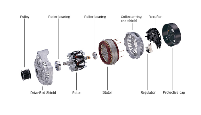
Modern alternators have an in-build rectification and regulator embedded in them. This makes the alternator able to maintain voltage as the electrical load shifts. The regulator monitors the voltage at battery terminal to determine electrical load. If the load increases, the voltage at battery terminal drops, and the regulator circuit supplies more current to the rotor field to increase the voltage back to prescribed value. And likewise if the load decreases, the voltage at battery terminal increases, and the regulator circuit reduces current to the rotor field to fine tune output. It is necessary to maintain the voltage to properly charge the battery without overcharging it, which reduces battery life.
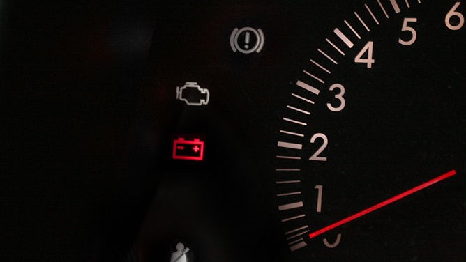
 The battery sign in your dash is there to alert the driver for faulty alternator output. If the sign is illuminated, either the Alternator is producing less voltage or more at the output. The common troubleshooting checklist is to initially check for broken drive belt at the pulley which might have snapped off. If everything visually looks in-order, hook up your battery to a volt meter (or Multi-meter set for measuring voltage) and check for terminal voltage with the engine off. Then crank the engine up and monitor change in terminal voltage, it should increase significantly. If the output drops after the engine has started, this means your alternator is producing low or no output. Rev up the engine and check for increase in output voltage. The voltage should rapidly increase with slight increment in engine speed and then should remain constant at 13.7-14.5v as you increase speed. If the output is not constant and voltage is increasing with increment in engine speed, your alternator is producing over voltage.
To verify for low or no output from the alternator, hold the engine speed over 2500rpm and disconnect the battery. If the engine stalls, the alternator is producing no output. If the engine remains on and stalls as you decrease engine speed, the alternator is producing low voltage. In case of under or over voltage, you need to replace the voltage regulator in the alternator. No output may account for faulty rectifier circuit or failed stater or rotor winding. If the battery sign is not being illuminated, but the alternator is still unable to keep the battery charged, you need to hook up your battery to volt meter and start your engine. Check for terminal voltage and then turn on all electrical loads and increase engine speed. If the output is not over 13v with full load, this indicates for a failing rotor winding or faulty regulator.
To test for disintegrated parts of an alternator you need a Multi-meter and schematic diagram for that particular Alternator model.
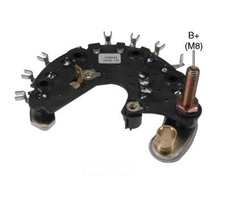 The rectifier section can be tested for continuity for diode connections. You need to look up the schematic for diode orientation and test for continuity from P to N but open circuit from N to P. Also look for short circuits to body. Generally the rectifier section is very rigid and has a long lifespan.
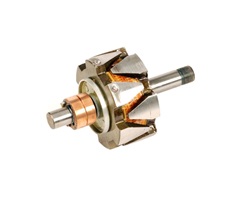 The rotor needs to be tested for resistance between terminals. The resistance should be generally between 2-6Ω. Check for open circuit between terminals and terminal to body short circuits. There should be no electrical path from terminal to body.
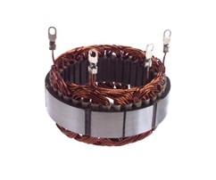 The stator has four terminals. Common terminal is grounded to the body of the alternator and other three are connected to the rectifier circuit. You need to check for resistance from common term to other three terminals. All should be same at 0-0.3Ω. Check for open circuits between terminals and terminal to body short circuits. There should be no electrical path from terminal to body.
 The voltage regulator cannot be bench tested easily. You need to hook it up back to the alternator and test it under electrical load and at engine speed.
Nice article bhai jaan.
main ne asal mein aaj kuch sikhaa pw blog se.
good work.
Much geek speak. I’m lovin’ it.
Thank you!
Very Nicely written
Great article….Instead of just writing about cars, you’re writing about each and every part about cars….amazing work Mr. Fahad Ghouri!!
Great work Pak Wheels….Good going……..
Keep these kinds of articles coming up about cars and stuff related to them.. instead of day dreaming about sth thats not and will not be (you know who I am talking about :p)
Running a alternator with battery disconnected is detrimental to the electrical system especially the electronic components.
Guys, I need help. I am building a electric bicycle, I wants to generate electricity from alternator through pedal power and its output will used to rotate another motor which will be placed with main chain. Can anyone suggest me alternator and motor specification??